Hardware Settings
LEDs
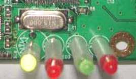 There are 4 LED connectors on the board. Depending on your product
design, they may not all have been
populated with LEDs. Nonetheless, the signal level on the pins can still be
used for diagnosis purpose.
There are 4 LED connectors on the board. Depending on your product
design, they may not all have been
populated with LEDs. Nonetheless, the signal level on the pins can still be
used for diagnosis purpose.
The first LED, namely network link, is a bi-color indicator, which is controlled by hardware PHY chip. It reflects the network link status. 10 M / 100 M / Inactive.
The other 3 LEDs - System, User 1 and User 2, have been assigned to carry information during the following two stages:
1. Booting. Controlled by
Boot Loader:
|
System LED |
ROM
Ok |
It turns on within the very first instructions in the FLASH ROM boot routine. If it is lit immediately after power on, it means that FLASH ROM is Ok. |
|
LED1 LED2 |
SDRAM
Ok |
They are turned on before the boot loader exits. If they work fine, it means SDRAM is Ok. |
2.
|
System LED |
System
Ok |
It flashes in a 1-second interval, which is cotrolled by the system service. If it stops flashing, it means either the system service is stopped or the system is crashed |
|
LED1 LED2 |
User
Defined |
On startup, the system service turns them into off state, and leaves the control to user software. Their meanings are freely defined by user programs. |
Jumper / Switch
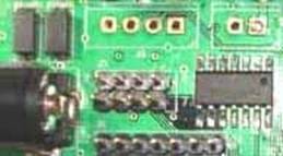
Every board has at least, but not limited to the following 3 jumpers or switches for hardware settings:
|
1 |
Hardware
Reset |
Manual hardware reset It generates a hardware reset to make all
hardware return to their initial states. |
|
2 |
Software
Reset / Restore
Default |
This jumper is normally connected to an external button which acts dual functions.
Press this button between 2 to 6 seconds and release it, will generate a hardware reset as if the jumper #1 has been set.
Press this button for more than 7 seconds, the system service will copy the default configuration
file /flash/config/app-default.ini to overwrite /flash/config/app.ini. And,
the device will be rebooted to make these settings effective. |
|
3 |
Debug
Mode |
The debug mode is designed for software debugging
during software development or production supervision. When the debug mode is
enabled: The console is fixed at 115200 bps, n, 8,
and 1 and is used as the control console of climax with a command shell
attached. It shows all the messages from boot loader, uClinux kernel and user
applications. In addtion, normal startup script in /flash/config/autorun.ini is bypassed. Therefore user programs are not executed. This feature is designed to help users to
recover from problematic programs which start automatically. |
Debug Mode ¡V Bootloader Monitor
When debug mode is set to enabled, right after power-on or hardware reset, bootloader shows the following message. After pressing ESC key, you can enter the bootloader monitor:
|
Metavert
Bootloader SDRAM:
16 MB CFI
Flash ROM found, total 8192 KB Region
#1 64 KB, 8 KB/sector Region
#2 8128 KB, 64 KB/sector Serial
Number: 3D820240 Press
ESC to enter debug mode . Commands: XF Xmodem
flash programming LS List images
in flash CLEAR Clear MTD user disk IP Set IP
address Q
Quit >
IP = 10.0.0.29 (assigned by DHCP server) |
The bootloader is quite simple, as there are only 5 commands:
XF - program flash with XMODEM protocol
LS - list images in flash
CLEAR ¡V erase user JFFS2 disk
IP -
set IP address (for TFTP transfer)
Q - resume normal linux boot procedure.
The detailed operations will be described in the later sections.